What Voltage Is An Electric Fence For Cattle . Like any electrical circuit, the positive wire carries the voltage and amps to the load (in this case the fence and anything that touches it). 9 rows upon contact with the fencing, animals will be shocked, remember the shock and know. Customer reviews Kuguo Voltage Tester Neon 10 from www.amazon.com How many volts is an electric cattle fence? How to construct an electric fence for cattle. Keep in mind that bigger is better, until the point that induction occurs.
Negative Voltage Converter Circuit. A negative voltage regulator is a circuit that is used to maintain the voltage of any specific negative voltage range. This circuit is developed from 555ic timer circuit.
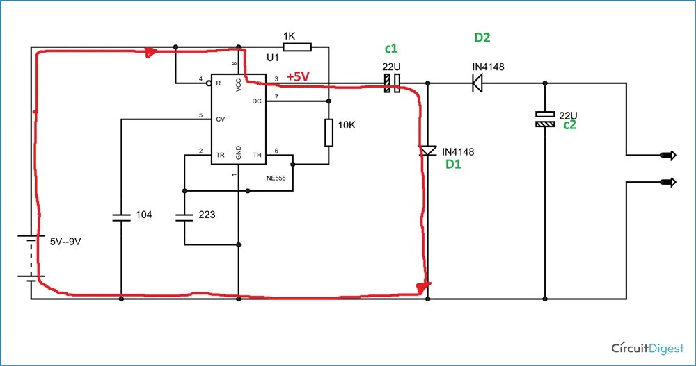
555 Timer Based Negative Voltage Generator from circuitdigest.com
Negative voltage generator circuit using ic 555. This is very common for amplifier circuits. This is the most popular application that use the max1044/icl7660.
This Circuit Is Developed From 555Ic Timer Circuit.
The power components of the typical boost converter with discrete circuit to generate a negative voltage is shown in figure 3. Synchronous buck converter, we can create a negative boost converter, as shown in fig. A negative 5 v supply circuit is easily built using a 7660 negative voltage converter ic.
So Negative Voltage Causes The Transistor To Turn Off.
Another place where negative voltage is used is for various transistors. An astable multivibrator oscillator circuit implemented by using timer ic 555 and then output square pulses are separated as negative output by using diode clipper. In this circuit signal oscillator is astable multivibrator and then voltage converter is diode clipper.
Now, To Convert A Synchronous Buck Regulator (Figure 1) Into An Inverter With Negative Output Voltage, Ti Suggests That The Inductor And The Output Capacitor Be Kept In The Same Locations As In The Original Buck Converter Circuit, But The Ground And Output Voltage Points Must Be Reversed In Order To Achieve A Negative Output Voltage, As Shown In Figure 2.
If you only need a small amount of negative rail, you can use a capacitive charge pump circuit like the 7660 or even make one with a spare timer output on your micro driving a capacitively isolated doubler. Here we have designed a simple negative voltage generator circuit. Other uses have been observed in lcd displays and
This Is A Negative Voltage Converter Circuit.
With only two noncritical external capacitors needed for the charge pump and charge reservoir functions, an input voltage within the range from 1.5 v to 10 v is converted to a complementary 555 timer ic is working as a negative voltage generator. This is very common for amplifier circuits.
Basically You Can Sample A Voltage That Is Negative On Pin 13 And 0V On Pin 7 Then, When You Toggle The Device The Charged Up Capacitor Gets Rearranged So That The Neg Terminal Of The Cap Is Connected (Via Pin 14) To Measurement 0V And The 0V Terminal Of The Cap Is Connected (Via Pin 8) To The Input Of The Adc.
It is my favourite approach for generating a negative voltage from a positive voltage and requires minimum components. These generate a negative output voltage which can be greater or smaller than the input voltage and provide an advantage over charge pumps. This cycle of the square wave will be generating both positive and negative voltage.


Comments
Post a Comment