What Voltage Is An Electric Fence For Cattle . Like any electrical circuit, the positive wire carries the voltage and amps to the load (in this case the fence and anything that touches it). 9 rows upon contact with the fencing, animals will be shocked, remember the shock and know. Customer reviews Kuguo Voltage Tester Neon 10 from www.amazon.com How many volts is an electric cattle fence? How to construct an electric fence for cattle. Keep in mind that bigger is better, until the point that induction occurs.
Voltage Divider Circuit Theory. In electronics, a voltage divider (also known as a potential divider) is a passive linear circuit that produces an output voltage (v out) that is a fraction of its input voltage (v in). As the name suggests, voltage divider, the circuit that divides the input voltage into the required levels.
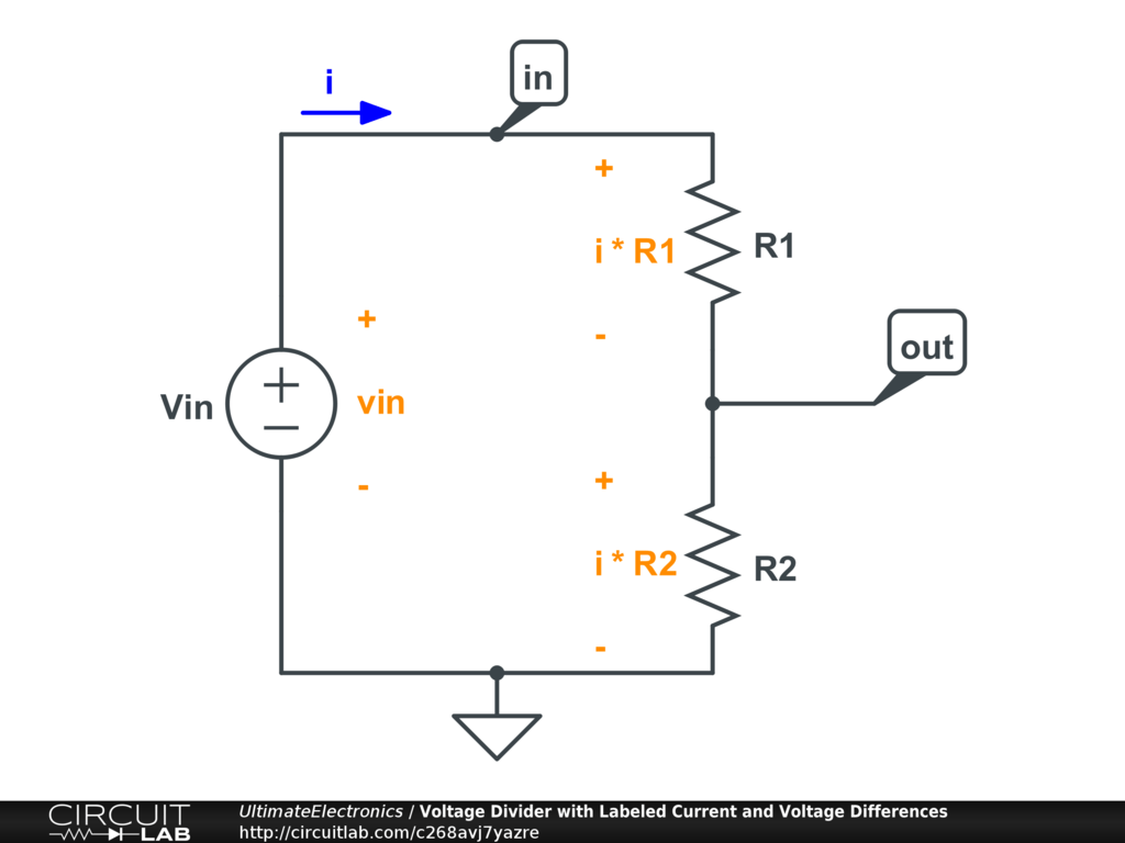
☑ Current Through A Resistor Divider from amicalegc-0607.blogspot.com
Current (r 1 & r 2) output voltage: V out can be used to drive a circuit that needs a voltage lower than v in. The input voltage is the voltage of the voltage source.
A Common Resistor Circuit Goes By The Nickname Voltage Divider.
A voltage divider is a simple series resistor circuit. A voltage divider is a very basic circuit when it comes to circuit design. In a series circuit, the same current flows through each resistance.
A Voltage Divider Is A Fundamental Circuit In The Field Of Electronics Which Can Produce A Portion Of Its Input Voltage As An Output.
In the previous article we developed an equation for voltage dividing, v o u t = v i n r 2 r 1 + r 2. V in = input voltage. Voltage divider circuits are useful in providing different voltage levels from a common supply voltage.
Applying This Rule Can Also Solve Simple Circuits Thoroughly The Main Concept Of This Voltage Divider Rule Is “ The Voltage Is Divided Between Two Resistors Which Are Connected In.
The output voltage is measured using a voltmeter. Voltage dividers are one of the very used circuits in electronics. With respect to a common point or ground, usually 0v, or it could be across a dual supply, for example ±5v, or ±12v, etc.
Using Just Two Series Resistors And An Input Voltage, We Can Create An Output Voltage That Is A Fraction Of The Input.
Therefore we can say that learning ohm’s law was like being introduced to the alphabets of a circuit then. The voltage divider rule is used to solve circuits to simplify the solution. Series voltage divider with parallel load current voltage dividers are often used to tap off part of the applied voltage for a load that needs less than the total voltage.
They Are Used To Generate Reference Points And New Circuit Branches With Inputs At A Particular Voltage.
It is applicable to all series circuits and combination circuits. The resistors are connected in series here and the voltage is given across these two resistors. It's output voltage is a fixed fraction of its input voltage.


Comments
Post a Comment