What Voltage Is An Electric Fence For Cattle . Like any electrical circuit, the positive wire carries the voltage and amps to the load (in this case the fence and anything that touches it). 9 rows upon contact with the fencing, animals will be shocked, remember the shock and know. Customer reviews Kuguo Voltage Tester Neon 10 from www.amazon.com How many volts is an electric cattle fence? How to construct an electric fence for cattle. Keep in mind that bigger is better, until the point that induction occurs.
Zener Diode Experiment Circuit Diagram. Choose the zener diode to start the experiment. Small zener diode voltage regulator circuit with pcb eleccircuit com diode voltage regulator circuit.
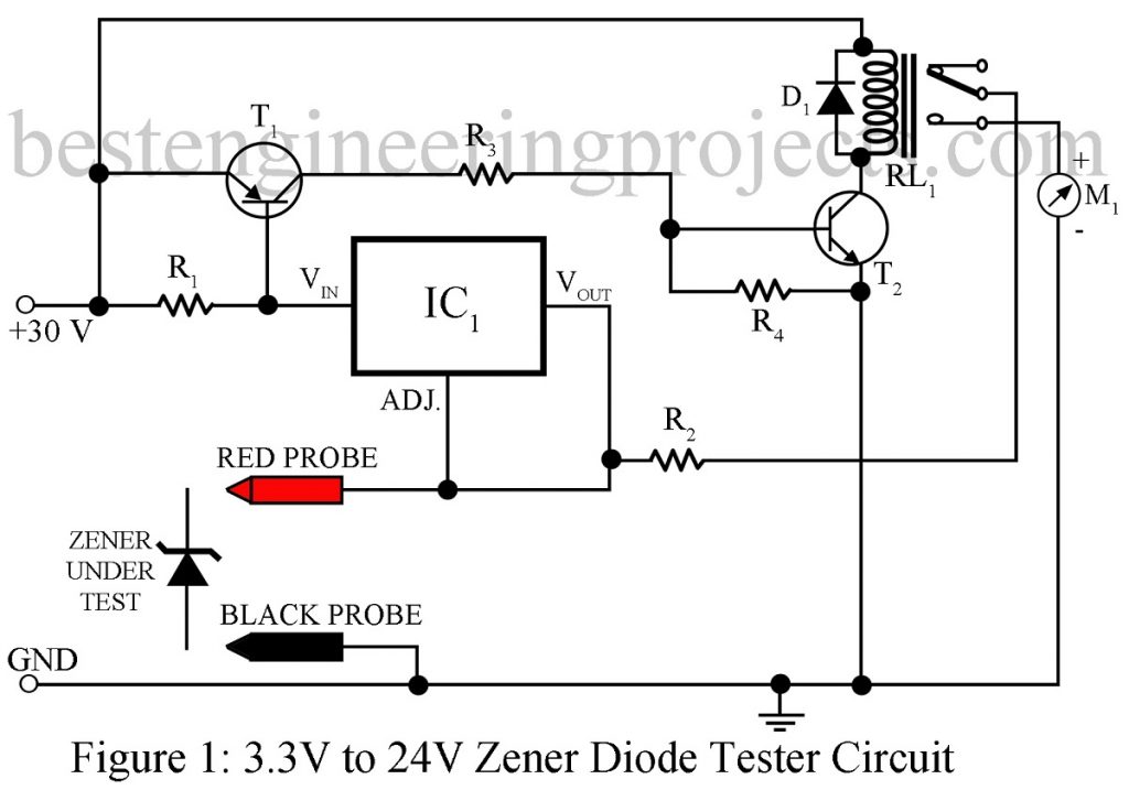
Zener Diode Tester Circuit Engineering Projects from bestengineeringprojects.com
When the diode is connected in forwarding bias diode acts as a normal diode. To see the circuit diagram, click on the 'show/hide circuit diagram' check box seen inside the simulator window. Also ensure that milliammeter is connected in series with zener diode having protective resistance and voltmeter is connected.
Small Zener Diode Voltage Regulator Circuit With Pcb Eleccircuit Com Diode Voltage Regulator Circuit.
First identify the terminals of zener diode, there will be a black colored circular band on one side of the zener diode. Fix the load resistance value by using load resistance slider. Also ensure that milliammeter is connected in series with zener diode having protective resistance and voltmeter is connected.
2 Zener Diode Characteristics Aim:
It has a particular voltage known as break down voltage, at which the diode break downs while reverse biased. This can help in associating one end with the other. In the case of normal diodes the diode damages at the break down voltage.
Select The Zener Diode From The Drop Down List.
The point at which the zener voltage triggers the current to flow through the diode can be very accurately controlled (to less than 1% tolerance) in the doping stage of the diodes semiconductor construction giving the diode a specific zener breakdown voltage, ( vz ) for example, 4.3v or 7.5v. The value of the series resistor is written as rs = (vl − vz)il. Zener breakdown voltage should be approximately close to the desired voltage we want.
To Find Zener Break Down Voltage In Reverse Biased Condition.
Name qty zener diode resistor 1k 1 1. When the reverse bias voltage is greater than a predetermined voltage then the zener breakdown voltage occurs. The above shown simple shunt regulator is not mostly effective and not feasible for higher current applicationz.
The Simple Circuit Diagram Is Displayed Below Where The Transistor Is Being Used As Emitter Follower.
The circuit diagram of a voltage regulator using a zener diode is shown: We need the following equipment: Zener diode circuit for psu with series transistor.


Comments
Post a Comment